
This guide will help you program serial communcations with the STM32F746NG embedded board. It may be useful for all STM products. It works primarily over USB, but it discusses using the serial pins too.
Initializing USART1 interface [#]
We are going to be using USART1, since this is the USART interface used for the USB pins:
/* USART1 init function */
void USART1_Init(void) {
  huart1.Instance = USART1;
  huart1.Init.BaudRate = 115200;
  huart1.Init.WordLength = UART_WORDLENGTH_8B;
  huart1.Init.StopBits = UART_STOPBITS_1;
  huart1.Init.Parity = UART_PARITY_NONE;
  huart1.Init.Mode = UART_MODE_TX_RX;
  huart1.Init.HwFlowCtl = UART_HWCONTROL_NONE;
  huart1.Init.OverSampling = UART_OVERSAMPLING_16;
  huart1.Init.OneBitSampling = UART_ONE_BIT_SAMPLE_DISABLE;
  huart1.AdvancedInit.AdvFeatureInit = UART_ADVFEATURE_NO_INIT;

    if (HAL_UART_Init(&huart1) != HAL_OK) {
    serial_err_handler();
  }
}
This uses a baud rate of 115200 (which is very high, 9600 seems to be more standard), word length as 8B with a single stop bit, with no parity. Remember these settings, they’ll need to be the same on the receiving end.
We also need to make a function to handle when serial communications couldn’t be set up:
void serial_err_handler () {
    serial_error = true ;
}
This simply sets a flag so we can see if it failed in debugging mode. Next, lets set up the GPIO pins associated with the USB serial interface
Initializing GPIO pins [#]
// must be called this. function declared in stm32f7xx_hal_uart.h
void HAL_UART_MspInit(UART_HandleTypeDef* huart) {

  __HAL_RCC_GPIOB_CLK_ENABLE();
  __HAL_RCC_GPIOA_CLK_ENABLE();

  GPIO_InitTypeDef GPIO_InitStruct;

    if(huart->Instance == USART1) {

    __HAL_RCC_USART1_CLK_ENABLE();

    GPIO_InitStruct.Pin = GPIO_PIN_7;
    GPIO_InitStruct.Mode = GPIO_MODE_AF_PP;
    GPIO_InitStruct.Pull = GPIO_PULLUP;
    GPIO_InitStruct.Speed = GPIO_SPEED_FREQ_VERY_HIGH;
    GPIO_InitStruct.Alternate = GPIO_AF7_USART1;
    HAL_GPIO_Init(GPIOB, &GPIO_InitStruct);

    GPIO_InitStruct.Pin = GPIO_PIN_9;
    GPIO_InitStruct.Mode = GPIO_MODE_AF_PP;
    GPIO_InitStruct.Pull = GPIO_PULLUP;
    GPIO_InitStruct.Speed = GPIO_SPEED_FREQ_VERY_HIGH;
    GPIO_InitStruct.Alternate = GPIO_AF7_USART1;
    HAL_GPIO_Init(GPIOA, &GPIO_InitStruct);
  }
}
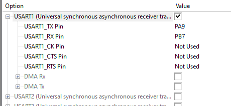
We’re setting up two pins, for the TX and RX pins needed (A9 and B7). We’re nearly done now, but we need to set up some values in RTE_Device.h (under ‘Device’ in the sidebar) otherwise keil will complain. Select ‘Configuration Wizard’ at the bottom (unless you REALLY like editing header files) and select the following options. Remember, we’re using USART1 with the USB pins:
Sending data [#]
We’re finally ready to write the main function. We can use sprintf() to format the text as you like:
int main(void) {
  USART1_Init();
  HAL_UART_MspInit(&huart1);

  char data[33];
  unsigned int c = 0;
  while (1) {
    sprintf(data, "hello world! %d\n", c++);
      HAL_UART_Transmit(&huart1, data, sizeof(data), 100);
  }
}
The function we’re looking to to send stuff is HAL_UART_Transmit(). If we want to data, we can use HAL_UART_Receive().
Recieving in Windows [#]
It’s now time to set up the windows PC for receiving the serial communications. First identify the COM port that the STM board is attached to. Right click on the start button, select ‘Device Manager’ and look under ‘Ports’. For me, it was COM6. We can use our old friend PUTTY to read the serial port:

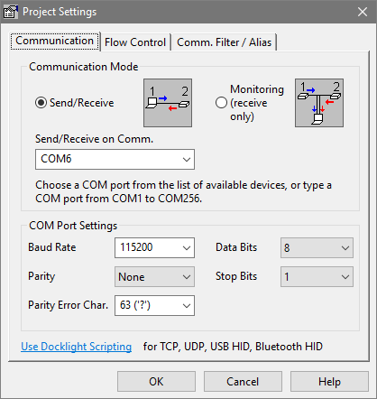
Remember to set the same baud speed as in the program.
We can also use Docklight:
If you want to do interesting stuff with this data, you’ll need to write a program on the PC end too. Its pretty easy to read a serial port with python:
import serial

ser = serial.Serial("COM6", 115200, timeout=1)
if not ser.isOpen():
    ser.open()

print('COM6 is open: ', ser.isOpen())
while True:
    print(ser.readline())
A more complicated example (with a GUI) is avaliable here.
Further reading [#]
Throughout this tutorial we’ve been using the USART1 over USB, but we could also use the physical pins if you wanted to. Looking at the documentation:
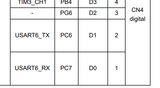
Physical pins D0 and D1 can be used, which are GPIO pins C7 and C6 respectively. They’re connected to USART6. You could use these pins and attach them to a raspberry pi’s serial pins, for example:
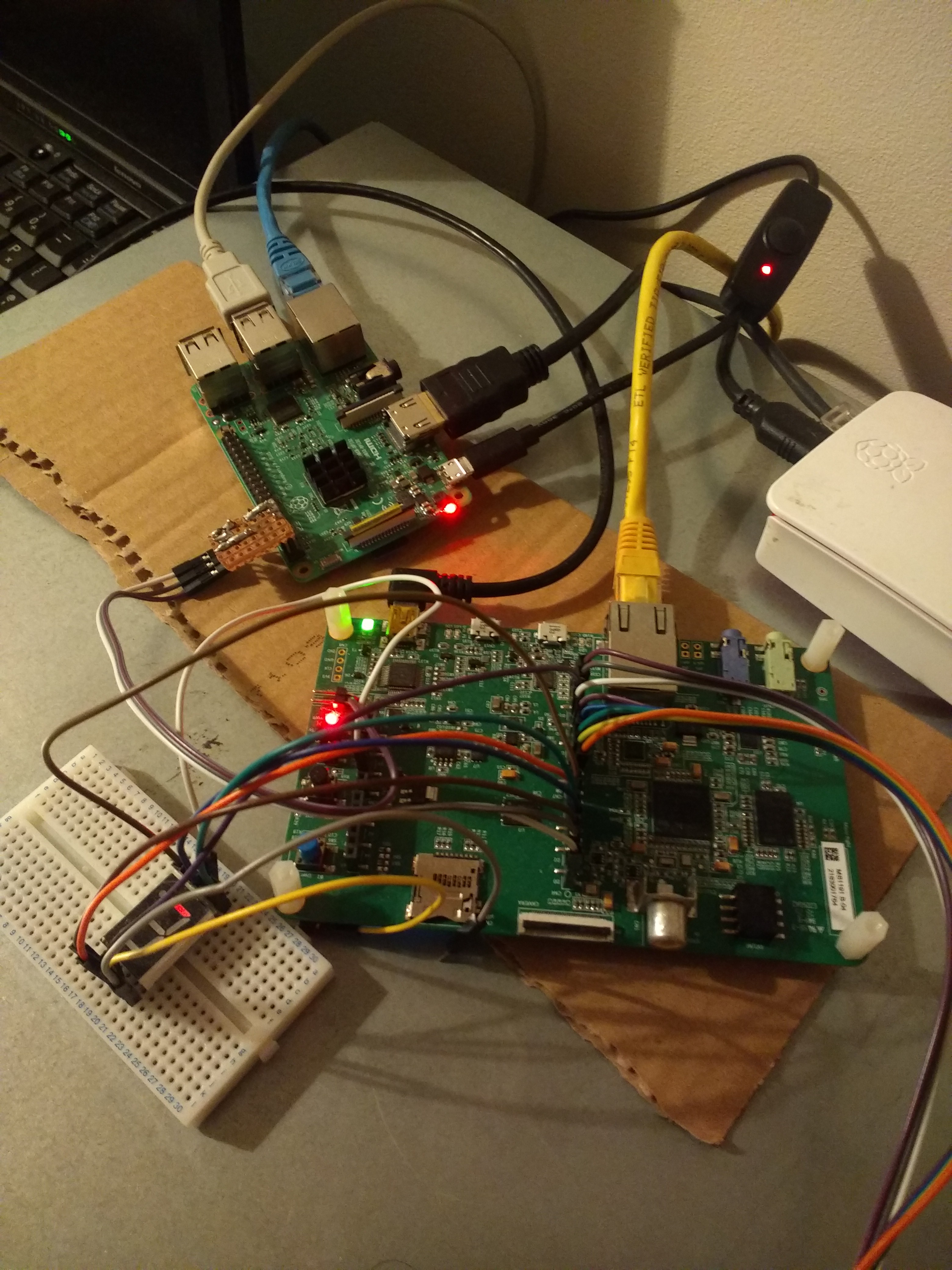
Although its important to mention that if you do choose to do this, you’ll need to make a little circuit with two resistors since the two boards work at different voltages and you don’t want to damage anything. You need to enable GPIO and serial on the raspberry pi with raspi-config. The serial interface you’re looking for is at /dev/ttyS0.